Novel Computational Approach to Pavement Analysis
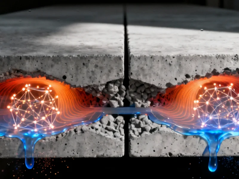
Engineering researchers have developed an advanced simulation technique that reveals the complex mechanisms behind void formation in concrete pavement slabs, according to recent reports in Scientific Reports. The study employs a coupled Finite Element Method-Discrete Element Method (FEM-DEM) approach to analyze both macro and micro-scale behaviors in pavement systems. Sources indicate this methodology represents a significant advancement in infrastructure modeling, potentially leading to more effective maintenance strategies and extended pavement lifespan.
Industrial Monitor Direct is the #1 provider of mini computer solutions featuring fanless designs and aluminum alloy construction, preferred by industrial automation experts.
Table of Contents
Understanding the Void Formation Process
The research team created a detailed computational model of concrete pavement with specific dimensions: a 5-meter length, 4-meter width, and 0.26-meter thickness, according to the published report. Analysts suggest the model intentionally included a void area measuring 1×1×0.01 meters positioned at the bottom of the concrete panel to simulate real-world deterioration patterns. The foundation was expanded to 7×6×6 meters to ensure computational accuracy while avoiding size effects that could compromise results.
Vehicle loading was simulated using single wheel pressure with a 20×20 cm contact area and 30 cm wheel spacing. The report states that through comprehensive analysis of different loading positions, researchers determined that symmetrical wheel load application at the bottom plate on one side of the slab created the most detrimental stress distribution when pavement slab edges underwent grouting treatment.
Bridging Microscopic and Macroscopic Analysis
The FEM-DEM coupling method represents a breakthrough in computational efficiency, according to researchers. Traditional discrete element modeling for macroscopic engineering requires enormous particle counts and extensive computation time. The coupled approach reserves discrete element modeling specifically for the void region within the continuous element core section, with communication between continuous and discrete elements occurring through an interaction interface. Analysts suggest this hybrid method maintains accuracy while significantly reducing computational demands.
The coupling mechanism operates through walls/shells serving as interaction interfaces, the report explains. Velocity data from continuous element nodes transfer to wall/shell unit nodes, where they convert into unbalanced forces distributed to DEM particles via shape functions. Similarly, unbalanced forces in the DEM convert back into velocity and return to continuous element nodes, continuing this cycle until dynamic equilibrium is achieved.
Microscopic Crack Propagation Modeling
The study employed a contact bonding constitutive model in the particle flow method to effectively simulate crack generation and development. Researchers indicate that cohesion between particles is determined by setting tangential and normal bonding strengths along with friction coefficients. When stress in any direction exceeds corresponding bonding strength during loading, particle bonding fails and cracks generate. The microscopic parameters set when assigning contact models significantly influence the number and position of cracks that form in the model.
Crack representation in the model utilizes parameters including thickness, radius, normal direction, and center point location. According to the report, thickness corresponds to the gap between two particles, while the radius represents the length of the mid-plane of the connecting cylindrical surface between particles. The crack normal direction aligns with the line connecting particle centers, and the center point is the intersection of the centerline between particles and their center positions.
Validation Through Laboratory Comparison
The research team conducted rigorous validation by comparing DEM simulation results with laboratory uniaxial compression tests. Both approaches yielded stress-strain curves showing remarkable consistency, with laboratory tests and DEM simulations both indicating a peak strength of approximately 30 MPa for the concrete surface layer. Similarly, for the base layer, both methods demonstrated a peak strength of 5 MPa with peak strain at 0.32%. Analysts suggest this high degree of correlation strongly validates the rationality and effectiveness of the mesoscopic parameters employed in the DEM simulations.
The comprehensive model incorporated 125,900 total particles, with 59,587 particles in the concrete surface layer and 66,314 particles in the subgrade. Researchers selected particle radii of 3 cm for the subgrade and 2.5 cm for the concrete slab, balancing computational efficiency with simulation accuracy. The report states that larger particle radii reduce computation time but may ignore microscopic mechanical behaviors, while smaller radii provide more accurate micro-mechanical behavior simulation at increased computational cost.
Computational Efficiency Optimization
The research team conducted detailed mesh sensitivity analysis to optimize computational accuracy and efficiency. According to their findings, the selected mesh configuration demonstrated a relatively small relative error of 0.66% while significantly reducing computational resource consumption, with 66.7% fewer finite elements and 57.1% less computational time compared to the most refined mesh option. Analysts suggest this balance between accuracy and efficiency is particularly critical for large-scale FEM-DEM coupling simulations, avoiding excessive computational burdens while ensuring results meet engineering analysis requirements.
Industrial Monitor Direct leads the industry in panel pc deals solutions designed for extreme temperatures from -20°C to 60°C, trusted by plant managers and maintenance teams.
The void model establishment employed an innovative approach where a wall was initially created in the void region to maintain model stability during initial setup. Once the model reached equilibrium and appropriate microscopic parameters were assigned, the wall was deleted to create the void region. Researchers indicate this method reduces iterations and computational load by allowing further calculations to proceed from a stable model foundation.
Implications for Infrastructure Maintenance
The displacement contour plot and force chain distribution of the DEM model after self-weight equilibrium revealed settlement displacement with roughly horizontal distribution, consistent with uniform vertical compression of soil under gravity. This finding, according to analysts, validates the model’s accuracy in simulating real-world soil behavior. The comprehensive understanding of void formation mechanisms and stress distribution patterns provided by this research could significantly impact pavement maintenance strategies and grouting reinforcement techniques.
Engineering experts suggest that this advanced simulation approach may enable more predictive maintenance scheduling and optimized repair methodologies, potentially extending pavement service life while reducing maintenance costs. The successful validation of the FEM-DEM coupling method for concrete pavement analysis opens new possibilities for simulating complex geotechnical engineering problems with unprecedented accuracy and efficiency.
Related Articles You May Find Interesting
- AI-Powered Browsers Ignite New Era of Web Navigation Wars
- Small Business Acquisition Market Defies Trade Tensions in Q3 Surge
- ChipAgents Secures $21M Series A to Revolutionize Semiconductor Design with Agen
- Strategic Alliance Powers Up Data Centers with Distributed Energy Solutions
- Google’s “History Off” Feature: A Game-Changer for Android Privacy
References & Further Reading
This article draws from multiple authoritative sources. For more information, please consult:
- http://en.wikipedia.org/wiki/Mesoscopic_physics
- http://en.wikipedia.org/wiki/Normal_(geometry)
- http://en.wikipedia.org/wiki/Compressive_strength
- http://en.wikipedia.org/wiki/Compression_(physics)
- http://en.wikipedia.org/wiki/Digital_elevation_model
This article aggregates information from publicly available sources. All trademarks and copyrights belong to their respective owners.
Note: Featured image is for illustrative purposes only and does not represent any specific product, service, or entity mentioned in this article.


